1931 Ford Model A Roadster

1931 Ford Model A Roadster

Monday, June 8, 2015

Roadster Rear Brakes

OK, Lets get back to the rear brakes.  If you remember the car had no emergency brakes on it for some unknown reason.  Thanks to some parts from Walt and leftovers from the rear end I got at the Charlotte Autofair, I had enough to rebuild the brakes correctly.  


The first picture is the old brake assembly on the right and the new one with emergency brakes on the left. 


The next picture is just a close up of how it all goes together.


The third picture is a shot of the backing plate with the service brake lever (long arm) and emergency brake lever (short arm with return spring).


The fourth pic is the rear spring shackle with two new grease fittings pressed in.


The fifth pic is LR brake assembly installed on the car and the sixth is the RR side. 


Number seven is the back side of the LR assembly on the car. 


The last picture is the brake drum, hub and wheel back on the car.


Wednesday, September 3, 2014

Subrails, Crosschannels and Floorpans

Today I decided to see if all the new sub frame parts and floor panels I have accumulated would actually  finish out the bottom of the body where it attaches to the frame.  I had to purchase  new subrails, cross channels, side curtain storage pans, seat risers, and some floorpans from the suppliers and a few originals  from Walt as there were none in the car when I got it.  I have no idea how this car stayed together with so much of the lower body rotted out when my family was driving this car in the sixties and seventies.  Sometimes we had five or six people riding in this car in high school and never knew how rusted it was.  I guess Henry built a heck of a strong car back then.


As you can see the half rail repair rails don't come as far forward as advertised, leaving a major rotted gap in the body subrail.  Since this is a roadster, this is the only structural section at the doors, keeping the body from flexing and the doors from popping open in a hard turn.  I have to either find longer subrails or fabricate a section to fill in the gap.  All the floor pans fit really well but I am missing the riser for the back of the drivers seat.  Since the car was upholstered without this piece, I have to make one to fit the existing seat back or modify the seat I have to fit the missing seat riser.  Having so much fun!  Steve

Finally In!

The differential is finally finished!


After preloading the pinion bearings and carrier bearings with shims to get the right tension on the bearings, I adjusted the gasket thickness on each side until I got a good pattern on the gears and correct backlash.  Next I put in the axles and spyder gears and safety wired the bolts on the carrier.  Installed the unit in the housings and torqued to specs.


Next big job is to install the main leaf spring and shackles so I can add the other leaves.  Greased up all the leaves and started assembling them.  It took four hands and a lot of clamps to get this strong spring back together. Good thing daughter Sarah was home to help!


     After getting the spring leaves together and the clamps around them it was time to install the unit in the car frame.  With Sarah's help and a jack we got her to fit nicely back under the cross member where we bolted it in.  This took longer than anything on the car so far but I hope a nice quiet  differential will be worth all the time and effort when it is finished.  Steve

Thursday, August 14, 2014

Differential Assembly Part 3

After finding out yesterday we needed shims under the carrier bearings to pre load the assembly, I removed the axle housings and took out the carrier assembly and pulled the bearings off of it.  I had two .005 shims but thought it would not be enough.  I had a roll of .003 shim stock so I decided to make some shims.  I made four .003 so each side would get a total of .011 in shims.


Installed shims on carrier housing and re installed the bearings.  


Then re installed the carrier and axle housings and torqued to specs.  This time the carrier locked up as it should have.


    Next I checked the housing gaskets for thickness and marked them.  


Now I can dis-assemble the rear end and use the different thickness gaskets to get my backlash correct on the gears.  Hopefully I won't have to repeat these steps with the pinion bearings but it might have to happen to get the gears meshed correctly.  Later, Steve


Wednesday, August 13, 2014

Differential Assembly Part 2


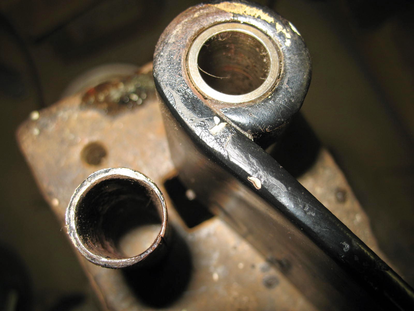
First pic is the spring eye on the anvil with the new bushing pressed in and the old one beside it.


  The bushings in the housings were really rusted in place and required heat from the torch to loosen them.  


After cooling they were driven out with the new tool.


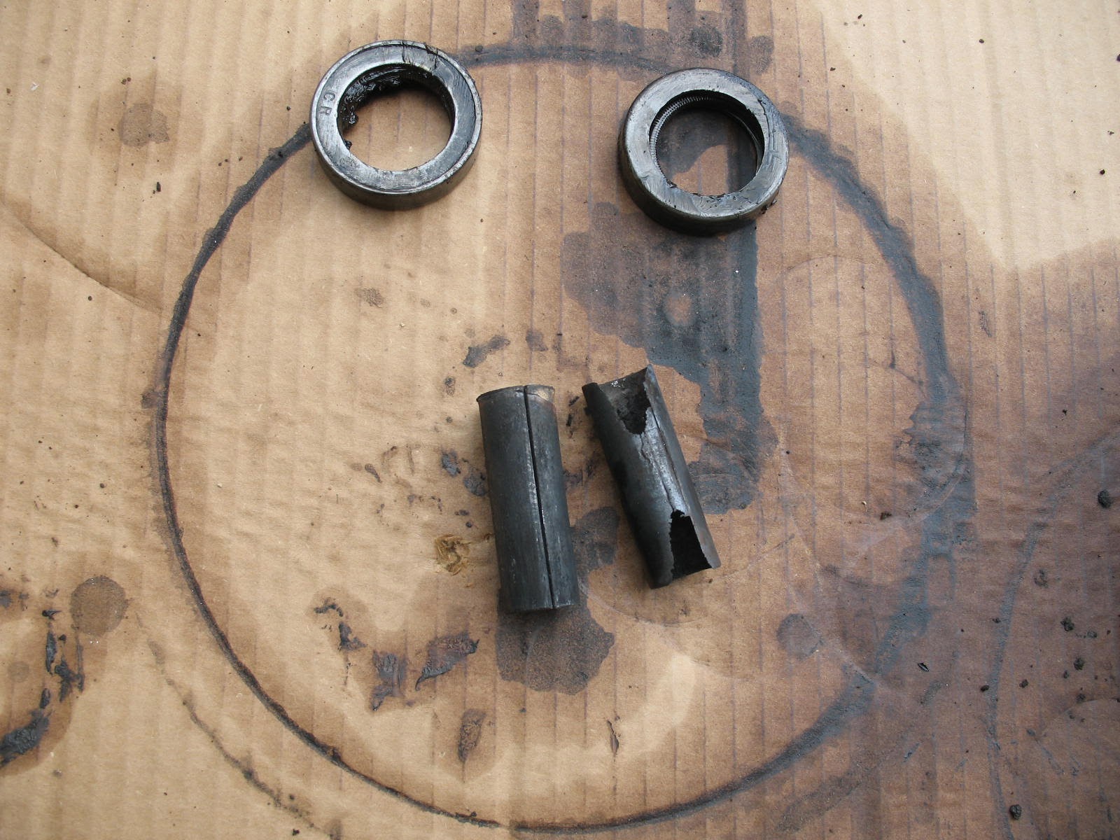
   Next is a pic of the old bushing and housing seals.  


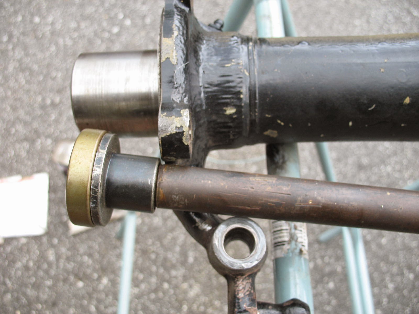
Then a pic of the new seal on an installation tool waiting to be driven into the housing. 


  Then a pic of the new bushing pressed into the housing and a pic of the new bushing and seal installation tool. 


Next is a pic of the right trumpet bolted to the banjo with the carrier housing and ring gear installed.  Then the left trumpet is bolted to the assembly to check the preload on the carrier assembly.  With no gaskets and all bolts torqued to specs it should have locked up the carrier, however it was too loose with the new carrier in the old housing so I will now have to remove the carrier bearings and add shims behind them to get the correct carrier preload before we can set the lash for the gears.  Getting closer, so stay tuned! Steve


Differential Assembly Part 1

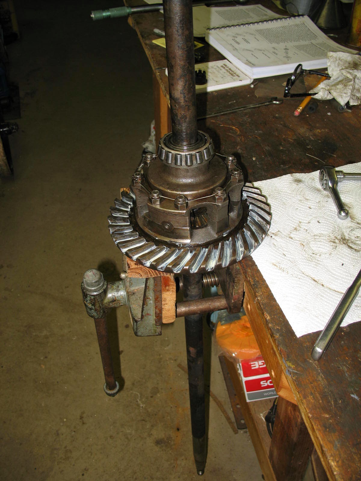
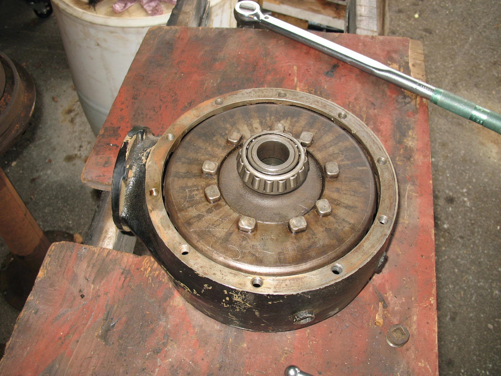
After determining that the gears were better on the differential that I bought at the swap meet, I needed to get the bearings off the carrier as they were shot.  I tried soaking and pressure from a puller for a month but they were stuck.  


Finally I decided to destroy the bearings and grind the inner race off the carrier, so the first three pics show that.  It seems that whoever took the last set of bearings off the donor differential, did so with a cold chisel instead of a puller and left some big burrs on the carrier.  Anyway got them off, cleaned up the burrs, and pressed on new ones.


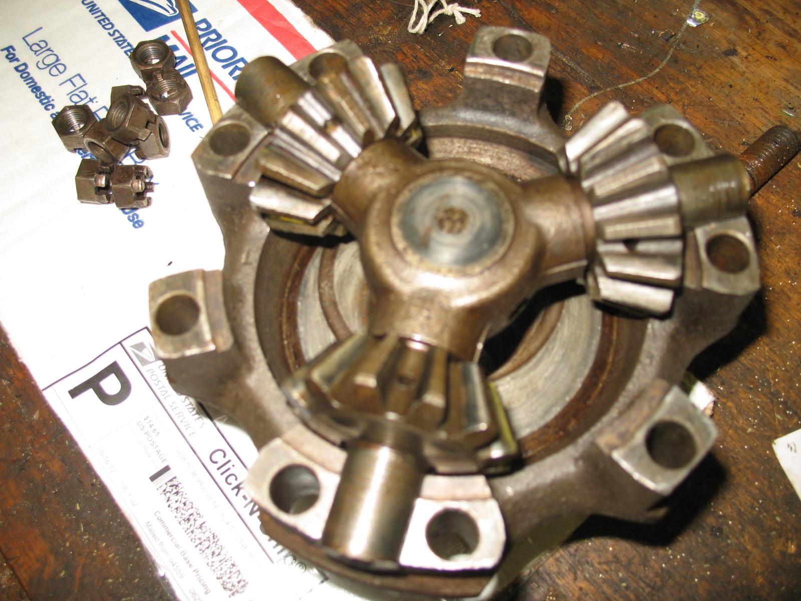
Next is a pic of the spyder gear in its housing and the top half of the housing.  You can see the date stamp of 4 29 31 in the housing so this differential is 3 months newer than the roadster.


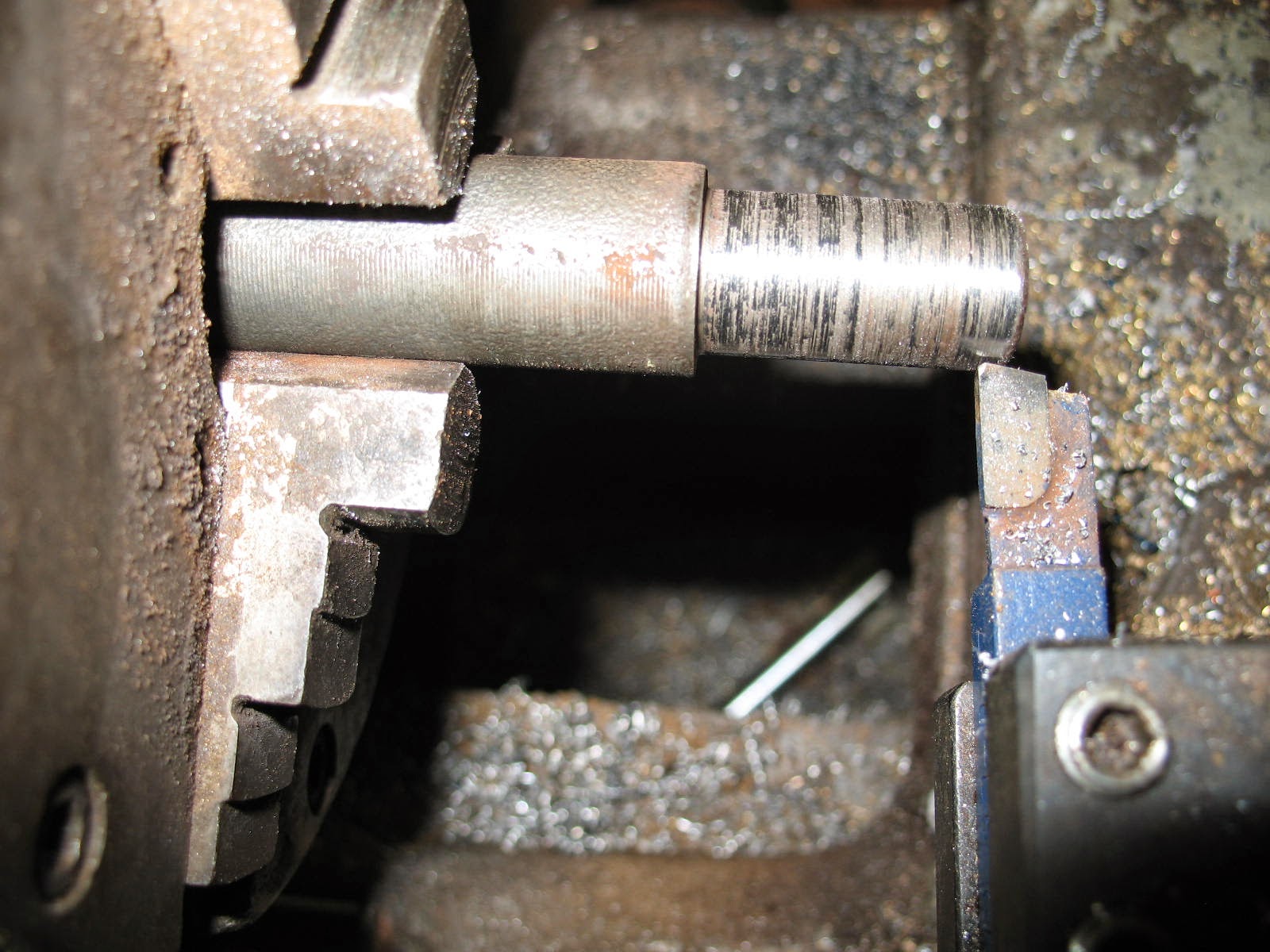
    I had to remove the old spring shackle bushings from the rear spring and differential housings and they were very stuck.  So I turned a bushing driver in the lathe and was able to drive them out of the springs with it but the ones in the housings were still frozen in place.  


You can see the driver in the spring eye on the anvil and in the housing in the next picture.