1931 Ford Model A Roadster

1931 Ford Model A Roadster

Wednesday, August 19, 2015

Driver's Door

I sort of knew we had a problem with the driver's door as it weighed twice as much as the other one.  Well, bondo spread over an inch thick all over the door is going to add pounds.  Throw in the window screen wire and you have a great unuseable door. Harry came by today to help speed up the restoration and we sanded the bondo out of the left door and quarter panel.  There is not much useable here!  It's either find a used drivers door or spend $ to get a new one.  Booo Hoooo!

Top of Door

Door Top

Door Corner at Lower Hinge

Inside Door Corner

Hinge Weld

Bondo Over 1-Inch Thick

Latch Welded In


Monday, August 17, 2015

Rear Corner Braces

The triangle rear corner braces support the rear quarter panels and tie the quarter braces, subrail, and quarters together along with attachment points for the curved inner panel below the rumble seat.

Cracks and Holes
Ready to Weld

Cracks

Extra Holes
  The originals were full of extra holes from someone using a torch to remove them because they had been welded together in addition to the original bolts, along with lots of stress cracks from years on the road.  

Old and New Corner Braces

They were so bad that I bought new ones to use but upon trying to fit them it became apparent that it would be easier to repair the originals than to make the new ones fit.  


So I welded up all the cracks and filled in the holes with leftover pieces cut out of the subrails.  Then I primed them and started to test fit them in the car.  


The last two pics show where they go on the car and how they tie the rear section of the body together.  I want to temporarily assemble the entire body before final riveting so I can adjust body parts as I go along to get the best fit possible.  Steve 

Wednesday, August 12, 2015

Body Work Continues

The rear panel below the rumble seat is held in place with machine screws to the curved inner panel on top and screws to the rear subframe channel at the bottom.  The panel has D nuts riveted in place for the screws but someone broke the heads off years ago so the last time the car was repaired, they punched new holes beside the D nuts and screwed it together with sheet metal screws.  

Wrong Screws

Tapped Hole and Metal Screw

Picture one and two shows the original broken off screw with the broken off sheet metal screws.  The panel has an inner brace crimped in place that I was able to remove to get to the back side of the screws and get them all out.  I then ran a tap through the D nuts and they were useable again.  Then I put the brace back in place.

New Screws

New Screws


   The bottom of this same panel bolts in place to the rear subframe channel.  Eight D nuts are riveted to the channel before an inner channel is welded to it.  All our D nuts were missing so they had to be replaced.  The D nuts have to come up from the bottom side and have a flange peened over to hold them in place.  Since there is now no access from the bottom I had to drill eight 1/2 holes in the channel to insert the D nuts.  I taped a D nut in place from the top to locate my hole and drilled all the way through, then removed the D nut and finished drilling from the bottom side.  I had a magnet just the right size to insert the D nut up from the bottom and then held it in place with a screw until I could get it to the vice and insert the channel over a piece of 1/2 steel rod to peen the nut.  

D Nut Hole

Picture 5 shows the channel with the missing D nuts.  

New Access Holes

Picture 6 shows the 1/2 access holes drilled in the bottom side.  

Magnetic D Nut Holder

Next is a D nut on the magnet.  

Bucking Tool in Vice

Next pic is the steel rod in the vice for peening the nut.  

On Vice With Bolt

Nut in Place for Peening

The next pic shows the channel on the steel rod with a bolt in the D nut to hold it in place until the steel rod is under it, then I removed the bolt and the next pic shows it in place ready to peen.  

Peened

Rear Subframe With New D Nuts

The next pic shows a D nut in place peened over with a new bolt in it and the last one shows the rear channel ready for bolting together.
    Next time we will repair the rear triangle braces that go on the ends of these panels to provide support for the rear quarter panels.  Steve


Monday, August 3, 2015

Body Alignment Check


The first picture is a close up of the subrail /crosschannel intersection showing body bolt #5 and the two different sized Cleco's installed.  


Next is me hanging the driver's door to check the spacing between the cowl and rear quarter panel.  This space is not adjustable once the quarter is riveted to the subrail, so it has to be correct.  


The next pic is the interior with both doors hung looking through the rumble seat opening.  
   Everything is aligned and fitting well now so I will remove the body parts and unbolt the subrails and cowl from the frame and one by one I will replace each Cleco with a rivet and using an air tool with a special waffle head rivet them together. There is a sequence to riveting the body together because in several places once you have riveted a panel in, you can't get to the back side of other rivets to buck them. Let's see if we can figure it out!


Cross Channels and Floor Pans

Side View

Rear Floor Pan


Rear Floor Pan


Front View


Curtain Pan and Rear Floor


Next the subrails were bolted to the frame using the body blocks inserted into the cross channels.  The rear cross channel was bolted again to the bumper/body support.  Then the rivet holes were drilled and the subrails were temporarily fastened together through the rivet holes with Cleco fasteners.
   
Next the floor pans were installed and drilled for riveting into the flange in the subrails and cross channels.  They too were fastened temporarily with the Cleco's.  The front pan is under the drivers seat and holds the sidecurtains for the top when not in use.  The rear panel is the footrest for the passengers in the rumble seat.  It is supposed to slope upward at the front edge to meet the drivers seat, but the seat I have was made to go all the way to the floor so in order to use the seat I used a flat pan which will also let me move the drivers seat rearward a few inches for a more spacious cab. 

Next I temporarily installed the body parts to make sure everything lines up before I start replacing the Cleco's with rivets.  It would be easy to make body adjustments now but once riveted together, it would be a major undertaking.

Monday, July 27, 2015

Roadster Subrails and Crosschannels Finished

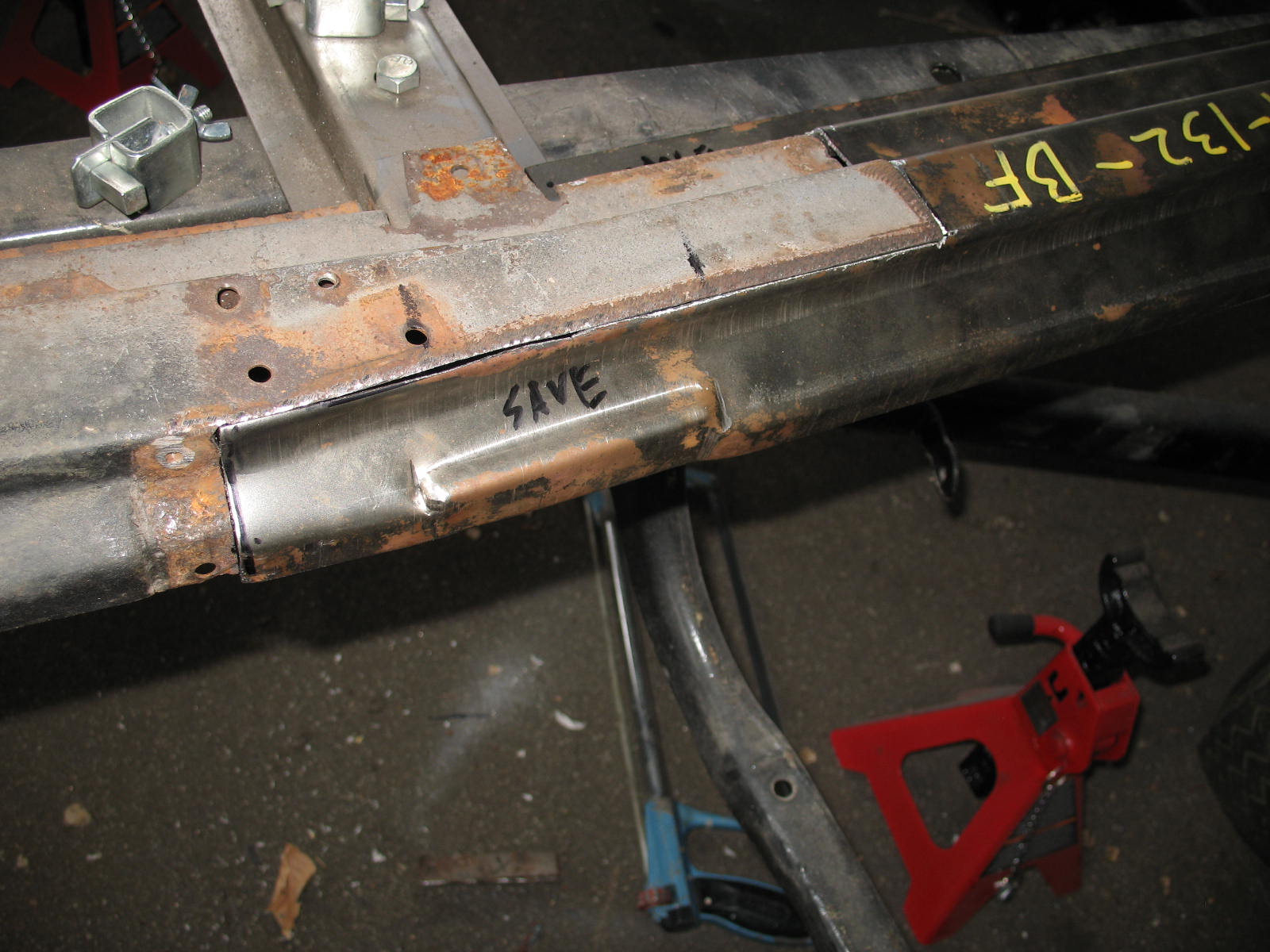
After getting longer subrails to repair the rusted original partial ones in the car, they had to be cut to fit.  I made long U shaped cuts for strength rather than just straight cuts and welds.  Each side was different depending on where the rust stopped.  


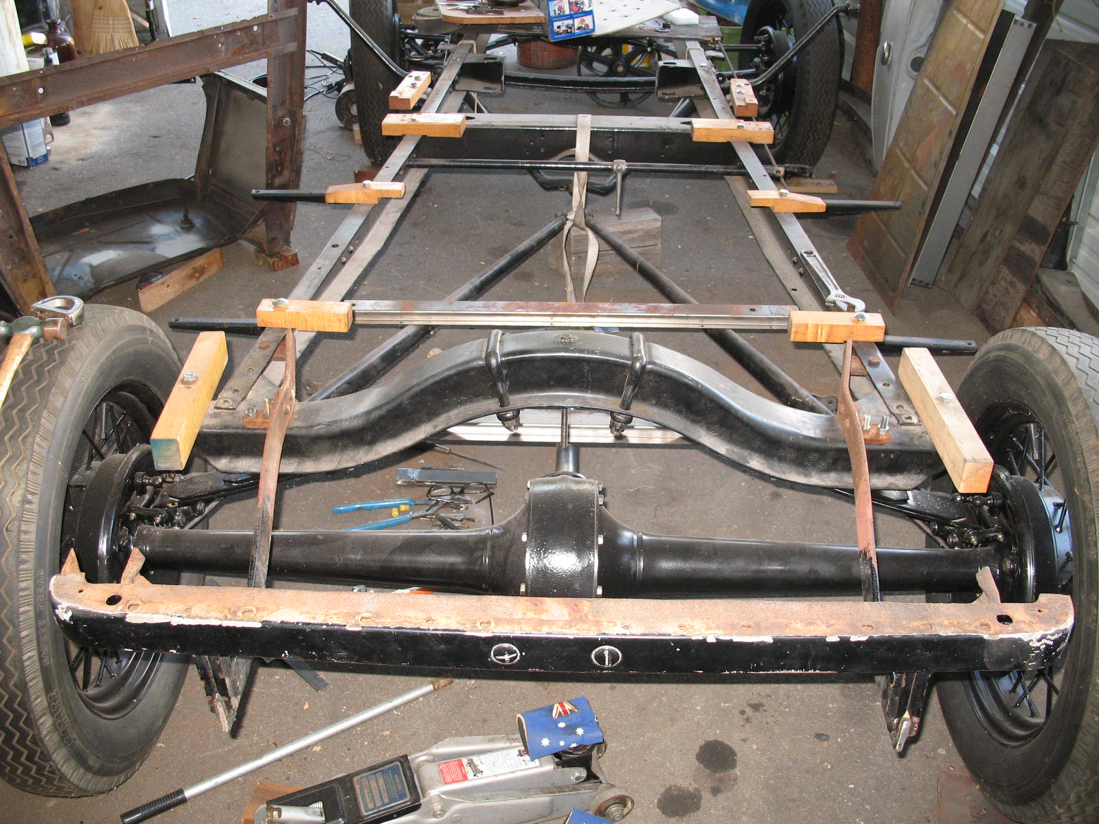
The first four pics are fitting the old and new sections together.  Getting the length correct is critical to having the body bolt together correctly so I installed the missing body blocks that hold the subrails and cross channels off the frame and bolted all the new metal together.  At the back of the car the bumper brackets/body mounts hold the last section of the body together as the frame stops at the differential.  So I mounted them to the car to locate the last cross channel only to find out they were off six inches.  It seems the car had been assembled years ago with a set of sedan bumper brackets that did not even connect with the rear subrail.  Luckily Walt had a set of roadster brackets he donated to the cause.  


The fifth pic is of the body blocks bolted in their correct location.


  Pic six and seven show the difference in the sedan and roadster brackets.  The one on the left is what was on the car and the one on the right is the correct one.  


The next pic is the old and new sections of the subrail welded together.  


The next pic is of the subrails and cowl inverted and ready to be sanded and primed.


Next two are the weld sanded and ready for priming.


________________________________________

The next six are the subrails primed before riveting the cross channels to them.  All will be bolted again to the body blocks and the cross channels will be riveted together.  Then  the floor pans will be  riveted in and the body can start coming together.